65 Results
View results:
Sort by:

Large-scale models are models which contain multiple dimensional scales and thus are demanding on computational power. This article will show you how to simplify and optimize the calculation of such models with respect to the desired results.

In RFEM 6 it is possible to define multilayer surface structures with the help of the “Multilayer Surfaces” add-on. Hence, if you have activated the add-on in the model’s Base Data, it is possible to define layer structures of any material model. You can also combine material models of, for example, isotropic and orthotropic materials.
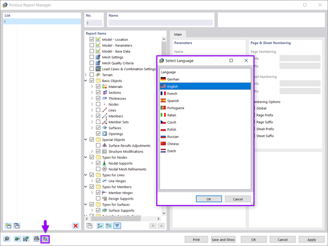
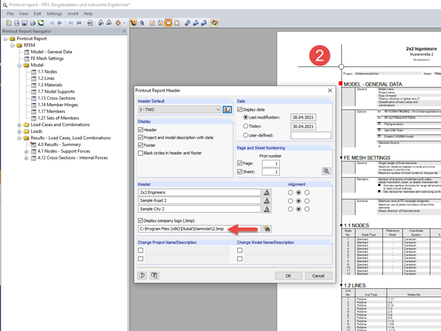
All data in RFEM 6 can be documented in a multilingual printout report. The design of the printout report is modern and has been highly optimized with respect to the previous (RFEM 5) generation of the program. Some of its most significant features are discussed in this article.

In accordance with Sect. 6.6.3.1.1 and Clause 10.14.1.2 of ACI 318-19 and CSA A23.3-19, respectively, RFEM effectively takes into consideration concrete member and surface stiffness reduction for various element types. Available selection types include cracked and uncracked walls, flat plates and slabs, beams, and columns. The multiplier factors available within the program are taken directly from Table 6.6.3.1.1(a) and Table 10.14.1.2.

The calculation of complex structures by means of finite element analysis software is generally performed on the entire model. However, the construction of such structures is a process carried out in multiple stages where the final state of the building is achieved by combining the separate structural parts. To avoid errors in the calculation of overall models, the influence of the construction process must be considered. In RFEM 6, this is possible using the Construction Stages Analysis (CSA) add-on.

You can use the selection options in the printout report to receive the detail results (in short or long form) to illustrate the individual buckling modes with the relevant buckling analysis.

The add-on modules for designing structural member components according to national, European, and international standards also show design results in addition to numerical output in tables graphically, as diagrams displayed on the framework.
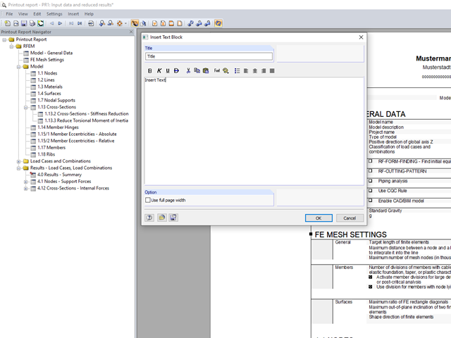
You can insert your own notes in the printout report. To do this, go to the printout report menu and click "Insert" → "Text Block."
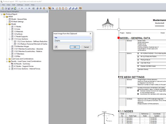
In RFEM and RSTAB, you can insert external images into the printout report.
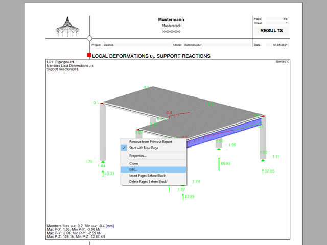
The printout report allows you to edit graphics subsequently.

RFEM and RSTAB save the input data, the FE mesh, the results, the printout reports, and the 3D gITF model preview, including all visual objects, in one file.
All Dlubal Software programs have access to the printout report environment.

The individually defined printout reports in an RFEM or RSTAB model can be displayed in different ways.
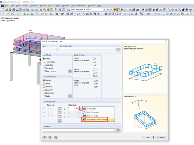
In RFEM and RSTAB, you can generate loads from multilayer composition.
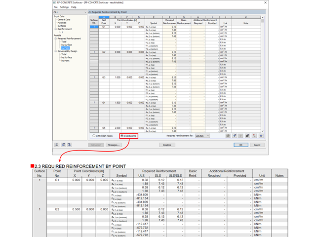
The results from RF‑CONCRETE Surfaces can be documented in tabular form in the printout report.

The additional loads from self‑weight are usually composed of several layers; for example, classic floor and ceiling layers in buildings, or road coatings for bridge constructions. When defining load definitions in RFEM and RSTAB, you can use the multi-layer load to define the individual layers with thickness and specific weight.

The SHAPE‑THIN and SHAPE‑MASSIVE cross-section programs are suitable for determining the cross-section properties of common thin-walled or thick-walled sections. These cross-section properties are also available for further analyses in RSTAB and RFEM.
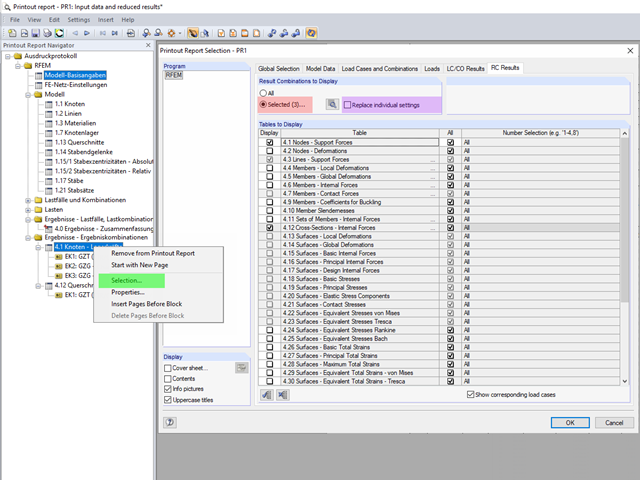
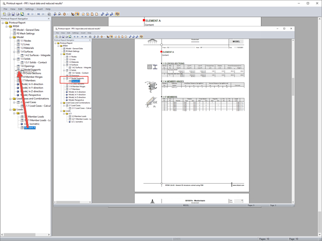
The content to be displayed in the loading and result tables can be managed in the global selection of the printout report (red).
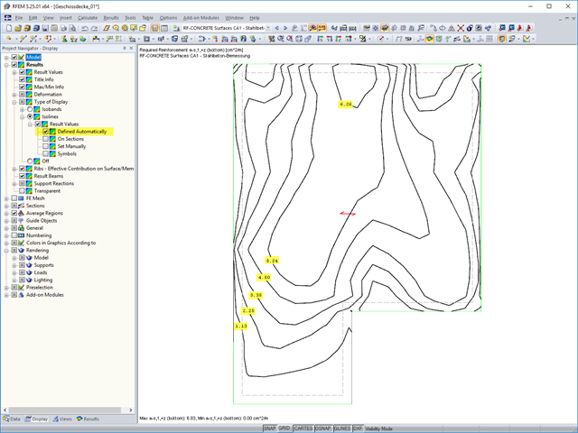
The results of an FEM calculation are usually documented by means of isobands and isolines in the graphical display of results. In the following, we will look at creating the results graphic for the black-and-white printout.
If you want to move individual elements or entire chapters in the printout report, there are various options.

In RFEM, RSTAB, and SHAPE-THIN, you can create user-defined print templates ("Printout Report Template") and printout headers ("Report Headers"). These templates can also be transferred to other computers and used there.
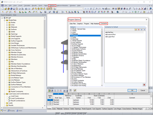
You can assign comments to each element in RFEM and RSTAB (structure element, load element, and so on). This can help to improve the overview and documentation of structures, as the comments appear in the printout report and, for example, certain objects can be filtered and displayed using the "Select Special" function.
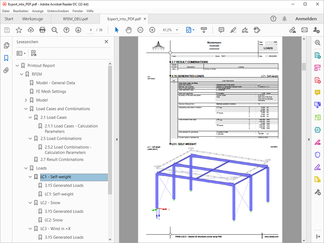
A PDF version of the printout report can be created in two ways. The most common way is to use a PDF printer that must be previously installed. The printer will be controlled like a real printer.

RF-/DYNAM Pro - Equivalent Loads allows you to determine the loads due to equivalent seismic loads according to the multi‑modal response spectrum method. In the example shown here, this was done for a multi‑mass oscillator.
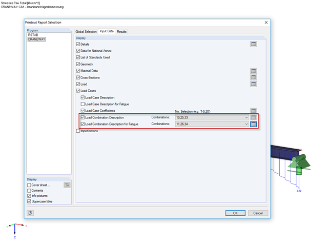
The selected increment of the load positions automatically increases the generated load combinations.
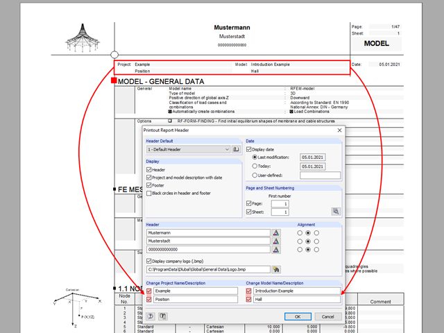
The name of the project/model from the General Data is shown in the header of the printout report by default. In RFEM 5 and RSTAB 8, the model name can be changed manually in the printout report independently of the actual name.
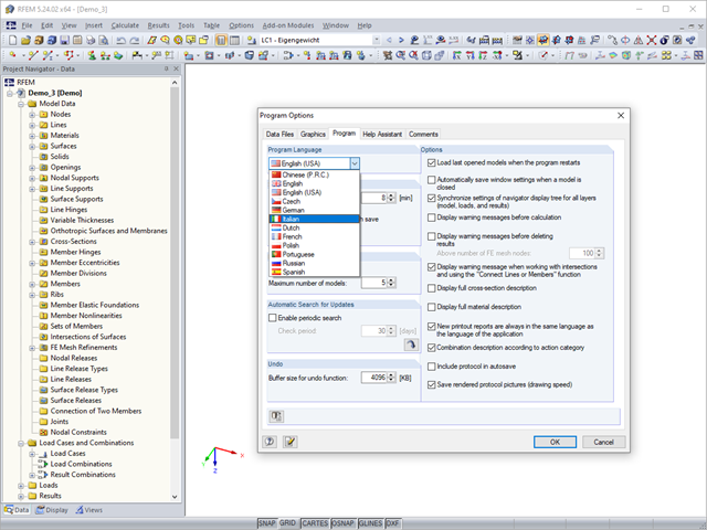
RFEM, RSTAB, and SHAPE-THIN are localized in eleven languages. All languages are available at no extra charge. The language of the program interface can be defined in the menu "Options" → "Program Options".

Designing rigid end plate connections is difficult for four-row connection geometries and multi-axis bending stresses, because there are no official design methods.

In order to consider inaccuracies regarding the position of masses in a response spectrum analysis, standards for seismic design specify rules that have to be applied in both the simplified and multi-modal response spectrum analyses. These rules describe the following general procedure: The story mass must be shifted by a certain eccentricity, which results in a torsional moment.
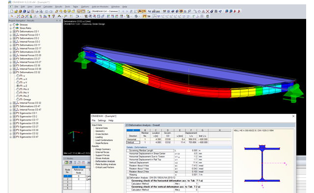
This article describes the different options for determining the allowable deformation of crane runway girders. Since multi-span beams and flexible lateral supports (sway bracing) are used in practice, this article will show how to select the correct method.